
Introduction: Why Speed and Feed Calculations Matter
In any milling operation, the rotating milling cutter moves against the workpiece at a specific speed, measured in surface feet per minute (SFM) or Surface Meters per Minute (SMM). This is referred to as the cutting speed.

The milling feed is the rate at which the workpiece moves towards the rotating milling cutter, typically measured in inches per minute (IPM) or millimeters per minute (mm/min). These two parameters together determine the trajectory and geometry of the cutting action, as well as the material removal rate.
Choosing suitable speeds and feeds is essential for achieving high quality machined surfaces while maximizing productivity. With incorrect speed and feed selections, issues like excessive tool wear, tool breakage, increased vibration and chatter, or poor surface finish can result.
By using a milling speed and feed calculator, machinists can determine the optimal combinations based on factors like tool diameter, workpiece material, number of flutes, and desired chip load per tooth. This eliminates guesswork and manual calculations.
In this guide, we will cover everything related to milling speeds and feeds, from basic concepts to step-by-step calculator usage, optimization strategies, and common mistakes to avoid.
Understanding Milling Speed and Feed
Defining Cutting Speed and Feed Rate
The cutting speed indicates the velocity at which the periphery of the milling cutter moves against the workpiece surface. It is defined as the surface feet per minute (SFM) value.
Feed rate refers to the linear distance the workpiece travels into the milling cutter per minute, measured in inches per minute (IPM). It determines the chip load or metal removal rate per cutting edge.
Together, the speed and feed influence key metrics like material removal rate, machining time, cutting forces, power requirements, and heat generation.
Speed, Feed, and Material Removal Rate
The product of feed rate and cutting speed determines the rate of material removal from the workpiece, referred to as the metal removal rate (MRR).
MRR = Feed Rate x Cutting Speed
A higher MRR leads to shorter machining time. However, maximum speeds and feeds depend on factors like workpiece material, tool specifications, rigidity of the setup, and required surface finish.
Influencing Factors for Speed and Feed Selection
Choosing milling speeds and feeds requires evaluating various parameters:
- Workpiece Material – Harder materials require lower speeds to handle cutting forces. Materials prone to work hardening also need controlled speeds and feeds.
- Tool Properties – Carbide and ceramic tools can withstand higher speeds than HSS tools. Coated tools may allow increased feeds.
- Rigidity – Heavier machines and setups can accommodate higher speeds and feeds than less rigid ones.
- Depth of Cut – Light depths of cut allow faster speeds than heavy roughing operations.
- Surface Finish – Fine finish requirements dictate lower speeds and feeds compared to roughing tasks.
- Coolants – Effective coolants may enable higher speeds and feeds than dry machining.
Machinists must balance these factors to determine optimal combinations. Speed and feed calculators automate these complex evaluations.
The Role of Calculators in Machining
In manual machine shops, machinists had to refer to printed speed and feed reference charts based on extensive field experience. These provided starting points for tweaking based on specific work conditions.
With CNC machining, more variables like multiple tool types, dynamic chip loads, and 3D surfacing came into play. Extensive trial and error was required to dial in speeds and feeds.
The evolution of digital speed and feed calculators dramatically simplified the process by considering all parameters affecting machining and providing scientifically calculated values.
Today’s advanced milling calculators only require basic inputs like tool data, workpiece material, and desired chip load. Complex physics-based algorithms instantly output ideal speed and feed combinations for specific scenarios.
By eliminating manual guesswork, these tools play a key role in achieving high productivity and economy in CNC milling applications. They are indispensable for modern machinists.
Components of a Milling Speed and Feed Calculator
To provide accurate speed and feed values, milling calculators require certain essential inputs from the user:
Tool Parameters
- Tool diameter
- Number of flutes
- Tool material and coating
Workpiece Properties
- Material type (aluminum, steel, titanium etc.)
- Hardness or strength values
Cutting Conditions
- Radial depth of cut
- Axial depth of cut
- Desired chip load per tooth
Machine Details
- Max spindle speed
- Available power
By combining these inputs, the software calculates suitable milling speeds and feed rates through advanced algorithms.
Additional factors like desired surface finish quality, presence of coolants, and rigidity of the setup may also be incorporated for enhanced precision.
Benefits of Using a Milling Speed and Feed Calculator
Instead of relying on outdated charts or trial and error, a milling speed and feed calculator provides major advantages:
Higher Productivity
Optimized speeds and feeds ensure maximum possible material removal rates leading to shorter cycle times.
Reduced Tool Wear
Ideal chip loads minimize cutting forces prolonging tool life. This reduces tooling costs.
Improved Surface Finish
Precision speed and feed selections provide greater control over surface finish.
Enhanced Accuracy
Correct chip loads minimize deflection, vibration, and chatter for superior dimensional accuracy.
Avoided Tool Breakage
Excessive feeds or speeds are prevented, eliminating catastrophic tool failures.
Lower Heat Generation
Controlled feeds and speeds dissipate heat effectively for less chance of heat damage.
For scenarios like high-performance carbide tool roughing of aluminum alloys, optimized speed and feed values can increase productivity by 40% or more compared to conservative estimates.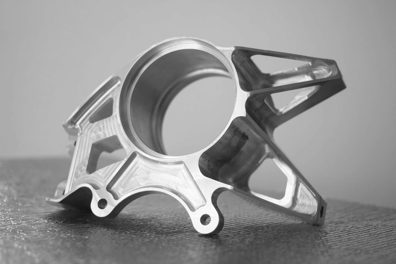
Step-by-Step Guide to Using a Milling Speed and Feed Calculator
Modern milling calculators are designed for quick and simple calculation of optimized speeds and feeds. Here is a step-by-step process:
1. Enter Cutting Tool Details
For the tool selected for the operation, input the diameter, number of flutes, material, and any coatings.
2. Define Workpiece Material
Select the specific material being machined from the calculator’s material database. Alternately, input the hardness on the Brinell or Rockwell scale.
3. Specify Cutting Conditions
Enter the desired radial and axial depth of cuts for the operation based on the toolpath.
4. Input Target Chip Load Per Tooth
Decide the ideal chip load (typically between 0.001–0.004”/tooth) depending on tool material and number of flutes.
5. Review Machine Power Limits
Check that the maximum power and top spindle speeds of the machine accommodate the desired range of speed/feed values.
6. Get Calculated Speed and Feed
The calculator leverages these inputs to instantly output the recommended speed and feed combinations with different options to select from.
7. Adjust for Surface Finish Needs
For fine finish requirements, tweak the speed and feed toward the lower end of the suggested range.
By following these steps for every new tool or operation, ideal speeds and feeds can be determined with ease.
Common Mistakes to Avoid
While machinists can gain tremendous advantage from using milling speed and feed calculators, some potential pitfalls need to be avoided:
- Not accounting for factors like rigidity limitations or poor chip evacuation ability that require feed reduction.
- Forgetting to decrease chip load and speed for a worn tool nearing the end of its life compared to a fresh tool.
- Leaving security factors on the low end rather than reducing speed and feed further for very light finishing requirements.
- Assuming one set of speed and feed values will work when transitioning between different tool diameters or flute counts.
- Forcing high feed rates on lower power machines that cannot provide sufficient torque at high chip loads.
- Not adjusting parameters for workpiece materials with highly inconsistent hardness or difficult microstructures.
By understanding these potential errors, machinists can judiciously interpret calculator outputs before implementation. Intelligent tweaking combined with experience helps get the most benefit from these tools.
Limitations of Speed and Feed Calculators
While milling speed and feed calculators continue to become more advanced, a few limitations need to be recognized:
- They cannot account for every possible scenario based on complex workpiece attributes, tool runout, vibration tendencies, etc. Some iteration may be required.
- Unique fixtures and workholding approaches may require departures from standard calculator outputs.
- Unusual cutting tool geometries or proprietary coatings may perform differently than a calculator predicts.
- Extensive familiarity with machines’ capabilities is still needed to judge optimum speed and feed combinations.
A calculator should never replace a machinist’s experience and judgment. The outputs serve as an accurate starting point for refinement based on subjective factors only a knowledgeable machinist can provide.
Choosing the Right Speed and Feed Calculator
To benefit fully from a milling calculator, certain selection criteria are recommended:
- Ability to store unlimited tools and material data for reuse.
- Frequent updates to expand material database and cutting models.
- Capability to save and reload prior speed/feed values for specific tools and materials.
- Accessible on smartphones and tablets in addition to desktop/laptop platforms.
- Outputs displayed in both IPM and metric units.
- Includes chip thinning models for trochoidal and HSM toolpaths.
- Accounts for factors like dynamic chip load.
- Provides flexible output options like SFM, IPM, RPM etc.
- Produced by a reputable company with extensive validation.
Quality calculators from brands like SolidCAM, Harvey Tool, and Machining Cloud meet these requirements for trusted and versatile speed and feed optimization.
Conclusion: Achieving Milling Success
Accurately calculating speed and feed rates is a vital requirement for productive, economical, and high performing milling operations. By removing the complexity of speed and feed determination through modern digital calculators, machinists can cut cycle times, reduce tooling costs, improve accuracy, and boost consistency dramatically compared to manual methods.
Equipped with this guide to milling calculator usage and best practices, manufacturers can leverage these invaluable tools to their fullest and take their milling processes to new heights of efficiency. The power to transform machining productivity is now at every machinist’s fingertips.