As a manufacturer of complex machined parts, every decision made during the design process impacts the time and cost needed to produce the part. Small tweaks across material selection, drawing specifications, geometry, and tolerances can significantly reduce machining time and expenses.
This article shares practical tips and considerations when designing parts for optimal manufacturability.
Material Selection
- Explore alternative materials beyond your standard go-to. More machinable alloys can reduce cycle times.
- Discuss options with your machinist – a less expensive material may work fine if strength is not critical.
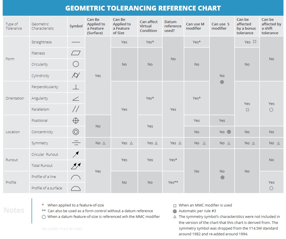
- Tight tolerances drive up costs. Only specify what’s truly functionally required.
- Match part size to raw material size when possible to minimize material waste.
Drawing Specifications
- Clearly label all parts with names and numbers to avoid ambiguity.
- Call out surface finishes needed rather than wide ranges that add complexity.
- Explain part functions and usage to enable customization of non-critical features.
- Dimension consistently from main datum planes to prevent tolerance stacking issues.
- Pay close attention to tolerances – don’t over-specify and create unnecessary challenges.
Part Geometry
- Design internal corners with standard endmill radii in mind for smooth machining.
- Use metric endmills to achieve more precise internal radii if needed.
- For threaded holes, allow drill depth to exceed thread depth to ease tapping and prevent chip buildup.
- Build assemblies from multiple smaller simple parts when possible rather than single large complex parts.

Continuous Collaboration
Work with your machinist from the beginning when designing new parts. Small tweaks early on prevent major change orders after production begins. Consider manufacturability at every design stage, not as an afterthought. From conceptualization to CNC Programming to CMM Inspection, all needs to be thought of.
Making informed design choices together with your manufacturing partner ensures you produce quality parts cost-effectively and avoid delays.