Chapter 4: CNC Programming for Thread Mills
Effective CNC programming is essential for productive thread milling operations. This chapter will explore G-code basics, manual and CAM programming methods, canned cycles, verification, and simulation for thread mills. Learning core programming principles and techniques prepares you to generate optimized NC code.
G-Code Basics
Understanding basic G-code structure and commands provides groundwork for programming thread milling operations. Key concepts include:
Machine Positioning
G00 – Rapid traverse motion in straight line to specified point
G01 – Linear feed motion at programmed feed rate to point
Plane Selection
G17 – Select XY plane for circular/arc interpolation
G18 – Select ZX plane
G19 – Select YZ plane
Feed Rate Mode
G93 – Inverse time feed mode. F values as time in seconds.
G94 – Units per minute feed mode. F values as conventional speed.
Distance Mode
G90 – Absolute distance mode using absolute coordinates
G91 – Incremental distance mode using distances from current position
Coordinate System
G54-G59 – Select coordinate system 1-6 from machine zero points
Tool Compensation
G40 – Cutter radius compensation cancel
G41 – Cutter compensation left of programmed path
G42 – Cutter compensation right of programmed path
Coolant Control
M7/M8 – Coolant ON
M9 – Coolant OFF
Spindle Control
M3 – Spindle clockwise rotation
M4 – Spindle counter-clockwise rotation
M5 – Spindle stop
“S” specifies spindle RPM
Common Canned Cycles
Many CNC systems include canned cycles to simplify programming of common operations like threading. Understanding available cycles accelerates programming:
G76 – Threading Cycle
Great for general thread milling. Defines key parameters like start point, depth, number of passes and taper angle.
G92 – Threading Cycle
Alternative threading cycle with similar capability. Useful if G76 not supported.
G74 – Left Hand Tapping Cycle
Generates program output for left hand tapping. Easily adapted for left hand threads.
Cycles for Drilling
Canned drilling cycles useful for hole preparation prior to threading.
Cycles for Boring
Boring to depth before threading helps ensure accuracy and quality.
Standardized canned cycles customize easily by setting values for the needed parameters. This simplifies programming vs manual code.
Manual CNC Programming Approaches
When canned cycles are unavailable or more flexibility needed, manual programming using G-code is required. Common approaches include:
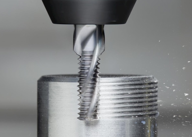
Helical Interpolation
Uses coordinated linear and circular interpolation to move along helical path, synchronizing axial and rotary axes. Requires 4-axis control.
Typical structure:
G00 X__ Y__ (Rapid to start point)
G01 Z__ F__ (Linear feed to depth)
G02/G03 X__ Y__ I__ J__ (CCW/CW circular feed)
Spiral Machining
Gradually ramps the toolpath radially in and down into the part in a 3-axis spiral motion. Simpler programming but limited applications.
Typical structure:
G00 X__ Y__ (Rapid to start point)
G01 Z__ F__ (Ramp down at fixed feed rate)
G02/G03 X__ Y__ I__ J__ (CCW/CW arc to spiral)
Linear Interpolation
Uses straight G01/G02/G03 moves in alternating linear patterns between thread flanks/faces to approximate the helical form.
More complex programming to calculate points but provides flexibility for custom forms.
CAM Programming for Thread Mills
Today most thread mill programming is done within CAM software rather than manual G-code. Major benefits of CAM programming include:
- Graphically visualize tool paths for verification
- CAM handles complex calculations automatically
- Easily test different tool path strategies
- Leverage libraries of proven cycle strategies
- Save time over manual programming
- Simulate and detect errors before machining
- Import part model geometry for programming
With a few clicks, CAM systems can generate optimized thread milling toolpath appropriate for the part model, eliminating tedious manual calculations.
Common CAM Programming Steps
Programming thread mills in CAM follows a straightforward workflow:
- Import/create part model
- Select optimal tool for application
- Define machining parameters and passes
- Select strategy (helix, circular, linear, etc) with required cut pattern
- Program cycle along thread geometry and ramp down to depth
- Set entry/retract moves avoiding reversals
- Post-process to output final code
- Simulate tool path for visualization
Following this sequence results in an effective NC program reflecting part features, tooling, and shop preferences.
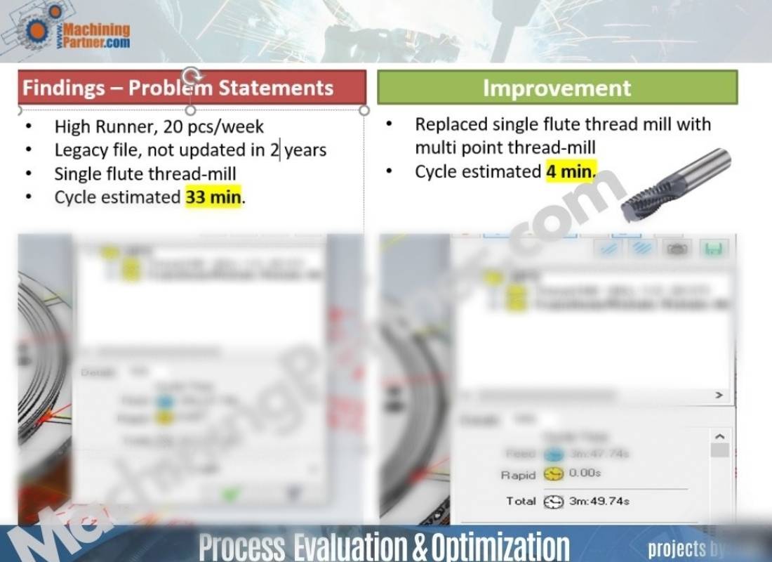
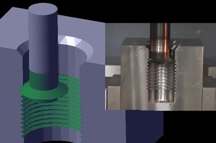
Verifying and Simulating Tool Paths
The final yet critical stage is confirming the program operates safely and as intended before running on the machine. This avoids errors and collisions.
Backplot – Check tool path visually in CAM or use backplot utility. Verify passes cover entire thread length.
G-code Review – Manually inspect code line-by-line to catch any bad coordinates, reversals etc.
Machine Simulation – Use machine simulator to validate complete sequence including entry, exit and movements.
Dry Run – If available, test program to confirm speeds, feeds and logic without cutting.
Leaving time to verify the program catches mistakes and provides confidence prior to production.
Thoroughly vetting NC programs before machining is imperative to avoid expensive equipment crashes or damage. Simulation and dry runs validate the code for safe execution.
Summary
Understanding the foundations of CNC programming equips you to effectively program thread milling operations. Follow basic G-code structure, utilize canned cycles where possible, and leverage CAM software for automated tool path generation. Always diligently validate programs through visual inspection, simulation and dry runs to verify safe operation before cutting metal. With these best practices, you can develop optimized NC code to maximize productivity and quality.